This is the second post in a series about the tech we used to put together Rift Core. If you aren’t familiar with Rift Core, you can check it out here. It’s an action RTS game about a squad of mechs who are desperately trying to save their world.
In this post, I’ll cover the decal system we used in the game. Rift Core has a lot of decals which indicate attacks, targets, movement, and so on. We found it a real challenge to blend these correctly into the terrain and into each other. I’ll describe the problems we ran into, and the solutions which we eventually used.
The Problem
Our original inspiration for the attack indicators came from Furi. Whenever an enemy in Furi winds up an area-of-effect attack, a stripe pattern appears on the ground indicating the danger zone.
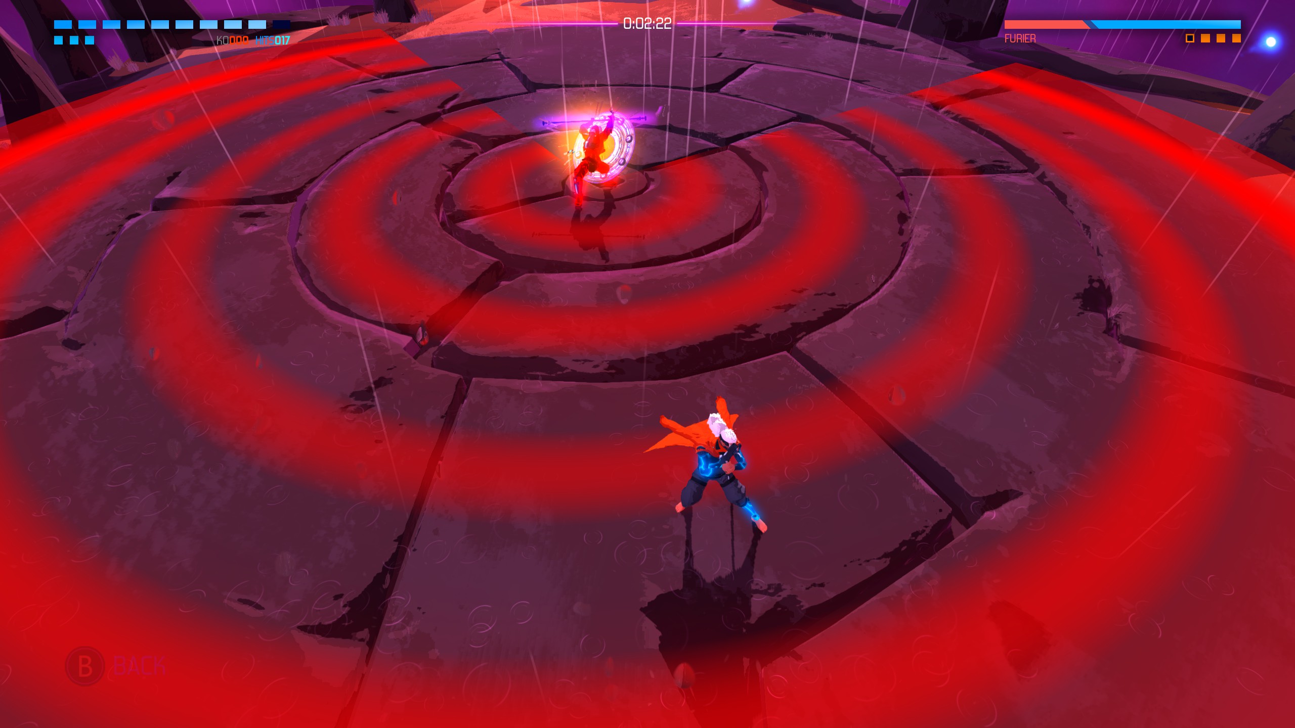
We wanted to produce something similar. Unfortunately, while the ground in Furi is almost always a flat plane, our low-poly ground has bumps to give it texture. That meant we couldn’t create flat geometry for the indicators. Instead, we decided to project the indicators onto the ground as decals.
The enemy attack indicators in the original Ludum Dare 43 jam submission were all separate Unity projectors. Each time an enemy would wind up an attack, we’d place a projector above the ground at the attack location to show where the attack would land.
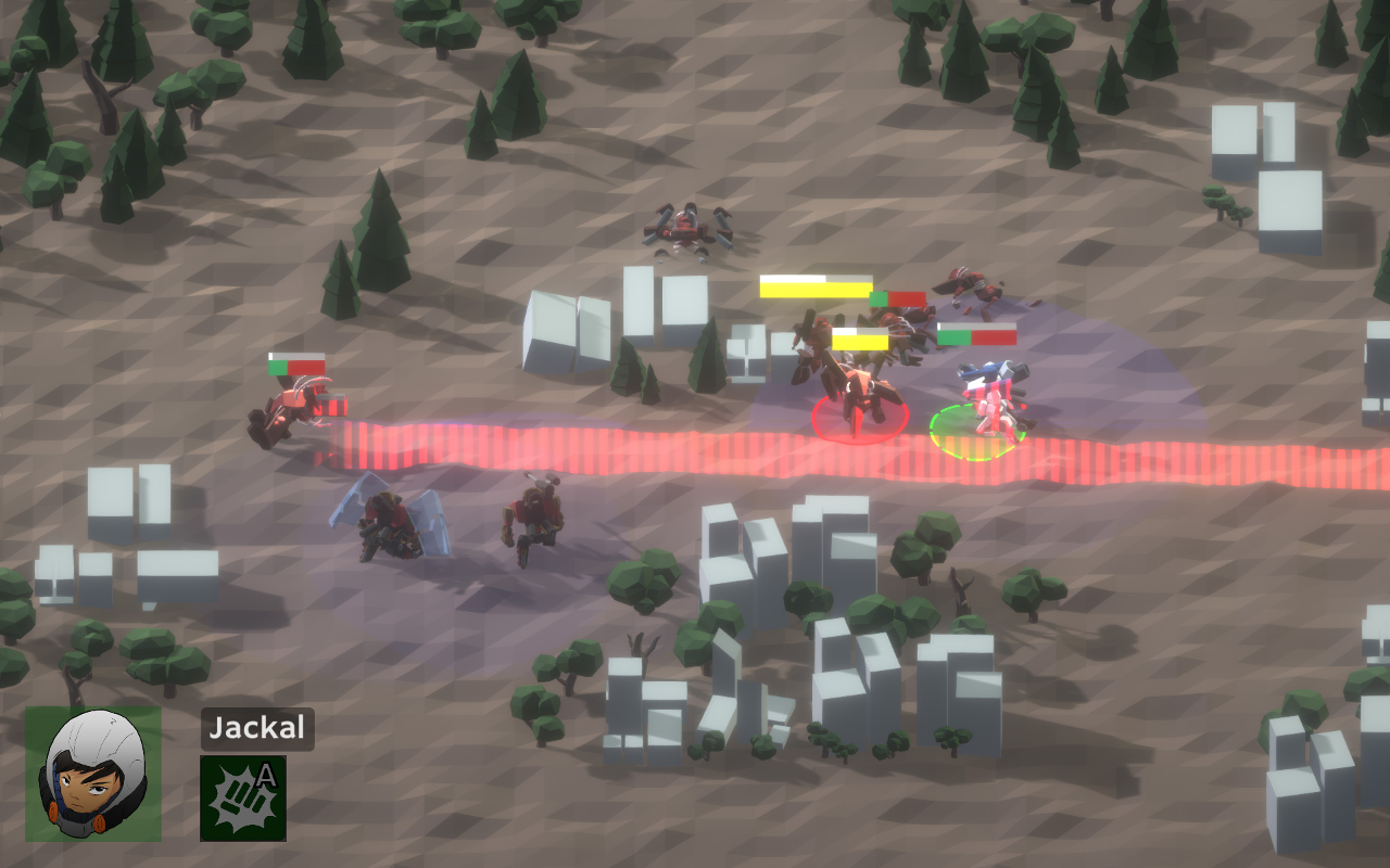
This approach had some benefits - namely, it was simple and effective. However, it came with two huge downsides:
- Performance was not good, as Unity projectors redraw all geometry within their frustum. With many enemies on screen all attacking at once, we would potentially re-draw the scene many times over.
- Shaders for projectors are difficult to write. Normal shaders are difficult enough to create, but when writing shaders for projector materials, one must keep in mind both object space and projector space. Additionally, you lose access to a lot of channels through which you can pass data, such as UVs or vertex colors, because you aren’t really drawing a new object - you’re redrawing some existing one.
The Solution
Here is a summary of what we ended up doing.
- Create real geometry for each attack indicator. For example, the cone attack indicator actually spawns a cone in the world which exists on the XZ plane and is oriented in the direction of the attack.
- Draw that geometry only with a separate “decal” camera. This decal camera is placed above the battlefield, encompasses the entire battlefield, and is oriented downward.
- Create a normal Unity projector with the same position, rotation, and orthographic size as the decal camera. The projector projects the output of the decal camera with a special shader.
Let’s break down each of those steps.
Real Geometry
If I switch off rendering for the ground, we can see that for each decal, there’s corresponding real geometry that exists in world space.
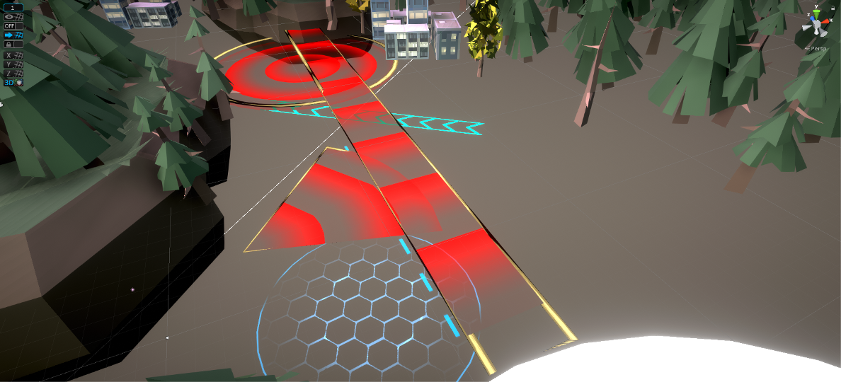
This solves our original problem #2 - that shaders are difficult to write. With real geometry, we can easily write shaders that do things like scroll UVs, or do more complicated things like in this shield range overlay.
Again - if our ground was flat, all we would need to do is place this geometry above the ground, alpha blend them, and we’d be finished. Since our ground isn’t flat, we need something more complicated.
Decal camera
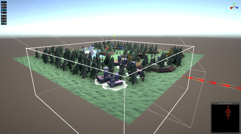
The main camera does not render any of this decal geometry. Instead, a special camera is dedicated to rendering these decals. This decal camera is set to orthographic, placed high above the ground, and encompasses the entire viewable area of the battlefield. I’ve thickened the bounds of this decal camera in the following image.
This decal camera renders not to the screen, but to a separate RenderTexture:
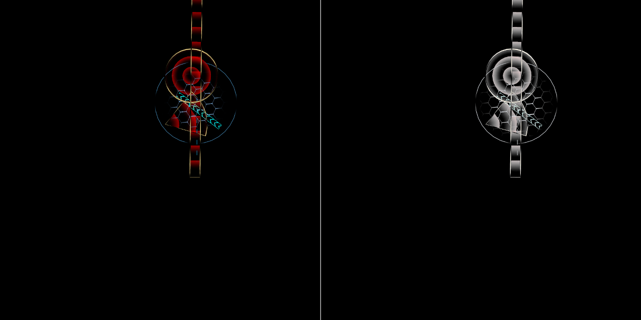
The image above shows the RGB channels on the left and the alpha channel on the right.
The camera’s clear flag is set to “Solid Color”. The color is set to black with zero alpha. This choice of color is important and it will become clear why, but intuitively: “black” and “no alpha” normally mean “don’t draw this”. Once we project this texture to the ground, we’ll use that data to mask out the decals.
A final note on this section: our RenderTexture is 2048x2048. You may notice some aliasing in the videos and pictures that follow since they are zoomed in, but in-game the aliasing is unnoticeable. Our main camera zooms out as the size of the battlefield grows, so even when the decal camera/projector becomes larger, the RenderTexture resolution doesn’t need to.
Projection
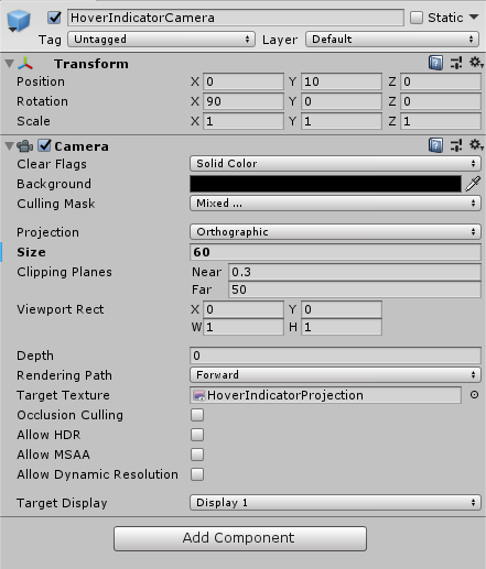
Now that we have this RenderTexture, we can project that to the ground. A projector with the same position, orientation, and orthographic size as the decal camera can take care of this. It’s important that the projector bounds exactly matches that of the decal camera, otherwise the render texture will be drawn in an incorrect position.
Here are the settings I use for the projector:

This projector uses typical projection shader math to sample the decal camera’s output texture. However, after getting that sample, figuring out how to blend that sample into the screen buffer turns out to be quite the headache.
Color blending woes
Our first try at the projector’s shader simply alpha-blended the texture’s contents with the screen buffer. The result was not quite right.
On the left side of the following video, the “fake” decal geometry is rendered with a camera using a clear color that closely matches the ground. On the right side is the actual decal which gets projected.
The projected decal is darker than we expected. The areas with partial transparency appear to tend more toward black. This turns out to be a problem with how we are doing blending within the shader.
To delve a bit deeper into what is going wrong, let’s take an example. Recall how normal transparent alpha blending works. Say we alpha-blend a color like \((1.0, 0, 0, 0.5)\) into the screen buffer, which contains the color \((0, 1.0, 0, 1.0)\):
\[(1.0, 0, 0) \cdot 0.5 + (0, 1.0, 0) \cdot (1 - 0.5) = (0.5, 0.5, 0)\]This is the result we get on the left side of the video above. The problem comes when we introduce that intermediate RenderTexture:
- First, we blend the decal color into the RenderTexture: \((1.0, 0, 0, 0.5) \, \textrm{alphablend} \, (0, 0, 0, 0) = (0.5, 0, 0, 0.5)\).
- Then, we blend that color into the color the screen buffer: \((0.5, 0, 0, 0.5) \, \textrm{alphablend} \, (0, 1.0, 0, 1.0) = (0.25, 0.5, 0, 1.0)\). This is darker than the expected result.
To solve this problem, we need to turn to an alpha compositing technique called “Premultiplied alpha”. I won’t go into details about premultiplied alpha here, but there’s many resources about it on the web. For our purposes, all we need to do is change the typical alpha-blend directive in our projection shader. Normal alpha blending looks like this:
Blend SrcAlpha OneMinusSrcAlpha
Whereas premultiplied alpha blending uses this directive:
Blend One OneMinusSrcAlpha
Remember that this is inside the projection shader. The blend mode for the decal geometry remains normal alpha blending.
If we take the same example as above, we can see that this works out to the correct result:
- \((1.0, 0, 0, 0.5) \, \textrm{alphablend} \, (0, 0, 0, 0) = (0.5, 0, 0, 0.5)\), as before.
- \((0.5, 0, 0, 0.5) \, \textrm{premulblend} \, (0, 1.0, 0, 1.0) = (0.5, 0.5, 0, 1.0)\). Or, expanded:
And that’s our expected result. Unbelievably, though, we ran into yet another problem. After changing the blend mode, the semi-transparent areas are now lighter than they should be:
This new problem is caused by the color space we use in Rift Core - the gamma color space. To learn more color spaces you can read the Unity documentation, but suffice to say it screws with the color values in your shaders in difficult-to-predict ways.
Gamma is the default color space in Unity, and isn’t recommended any longer for games targeting high-spec machines. Unfortunately for us, we didn’t know this until it was too late to change it. We would have had to tweak many, many other parameters in our project to change to Linear.
I ended up simply tweaking the final color output of the shader until it got us close enough to the right thing:
Finally, the colors look reasonable. This shader with tweaked colors is what we use in Rift Core today. Note that if your project is already using Linear color space, you probably won’t need this extra color tweak.
If you’d like to see the final projection shader, I’ve posted it as a gist.
Usage
That about covers the details of the decal system. With this system, to produce a new decal, all I need to do is:
- Create geometry for the decal & make it a prefab
- Instantiate that prefab at runtime under the ground where I want the decal to show up
Here’s a quick video breakdown of one example decal, our cone attack indicators.
Final Thoughts
I’ve covered the major pros with this system, but there are some cons too.
- It’s only suitable for use in small, contained scenes like those in Rift Core. If the camera was able to move, maintaining good-looking decals would require the RenderTexture to grow prohibitively large. In this case I’d probably use deferred decals, or somehow else translate this system to screen-space instead of world-space.
- We can’t use surface shaders on the decal geometry. Surface shaders automatically apply a
ColorMask RGBdirective, but we need the decal shaders to write to the decal RenderTexture’s alpha channel so they can be masked. Fortunately, lighting is unnecessary for the decals we wanted so it’s mostly a non-issue - we wrote plain CG shaders instead.
In the next post, I’ll talk about one specific decal that I thought was cool: the shield range indicator. Thanks for reading.